PERIODIC MAINTENANCE
EAS21030
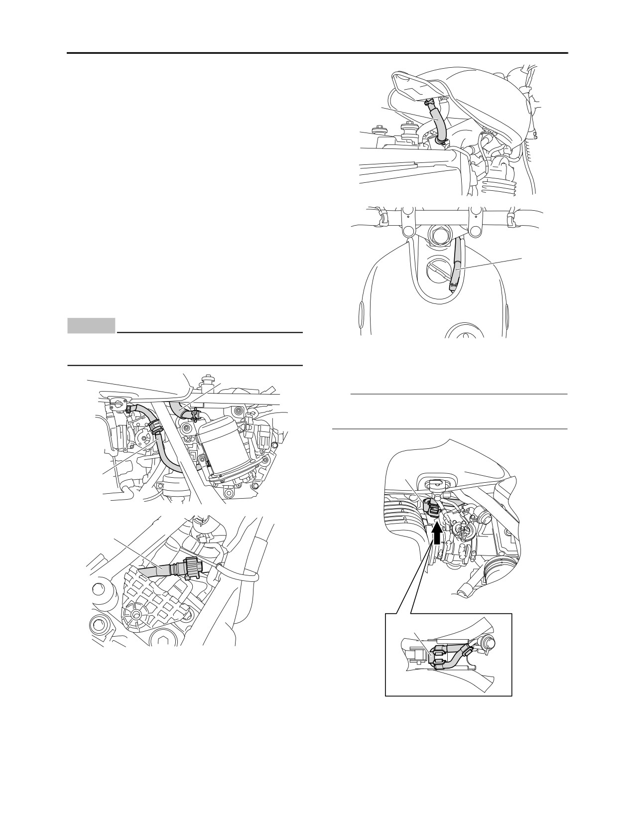
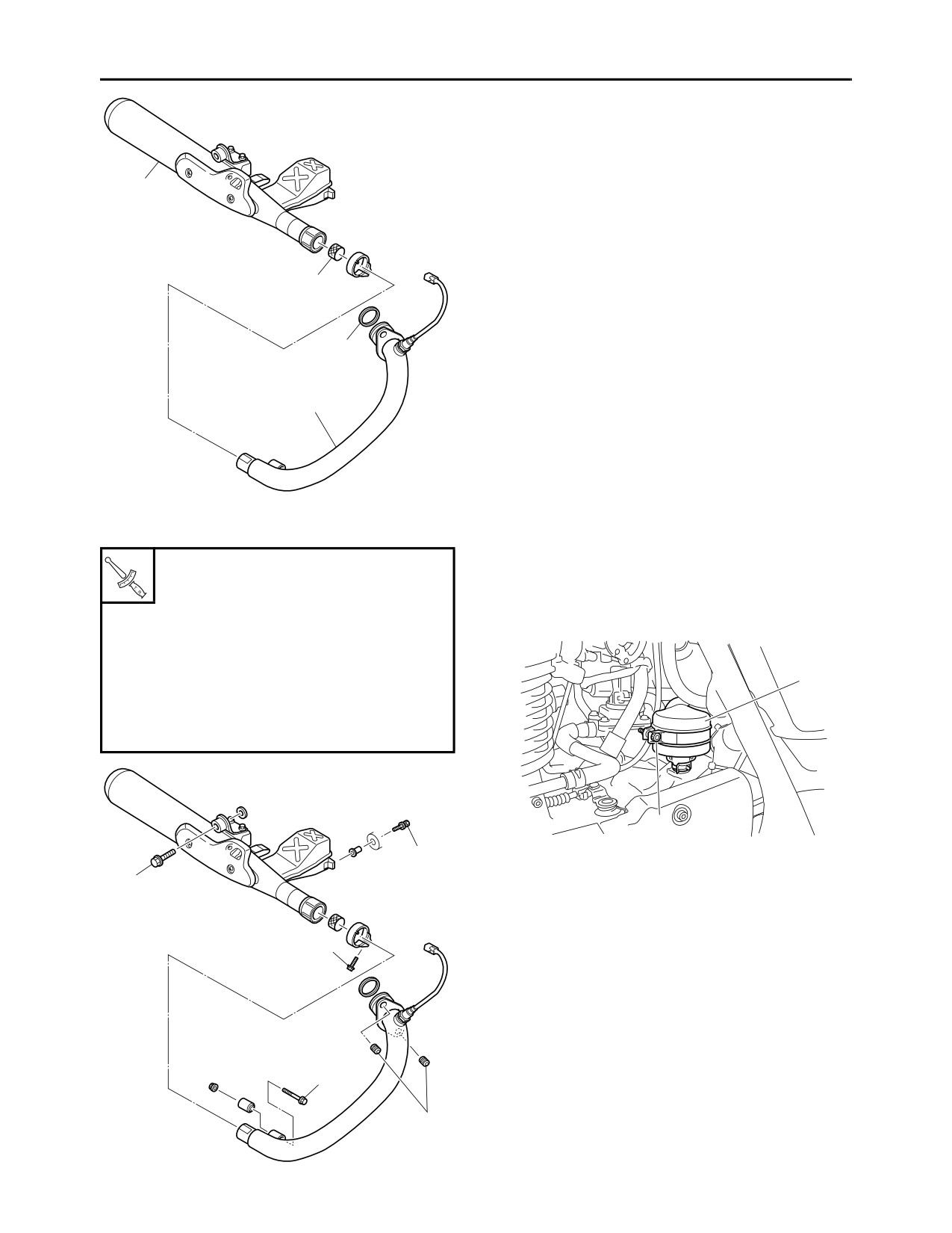
CHECKING THE FUEL LINE
The following procedure applies to all of the fuel,
vacuum and breather hoses.
4
1. Remove:
• Seat
• Side cover (left)
Refer to “GENERAL CHASSIS” on page 4-1.
• Fuel tank
Refer to “FUEL TANK” on page 6-1.
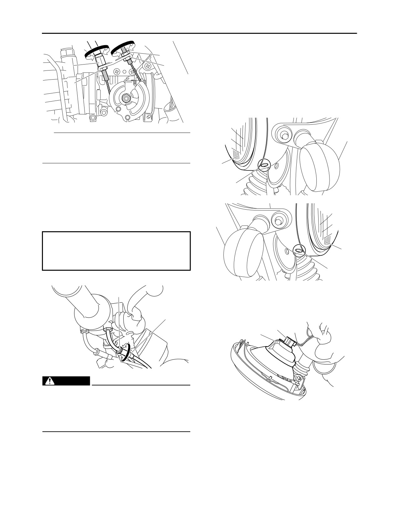
2. Check:
• Fuel hose (fuel tank-fuel pump case) “1”
• Pump case breather hose (fuel pump case-
fuel tank) “2”
• Fuel hose (fuel pump-fuel rail) “3”
5
• Fuel hose (pressure regulator-fuel tank) “4”
• Fuel tank breather hose “5”
Cracks/damage Replace.
Loose connections Connect properly.
ECA14940
NOTICE
Make sure the fuel tank breather hose is rout-
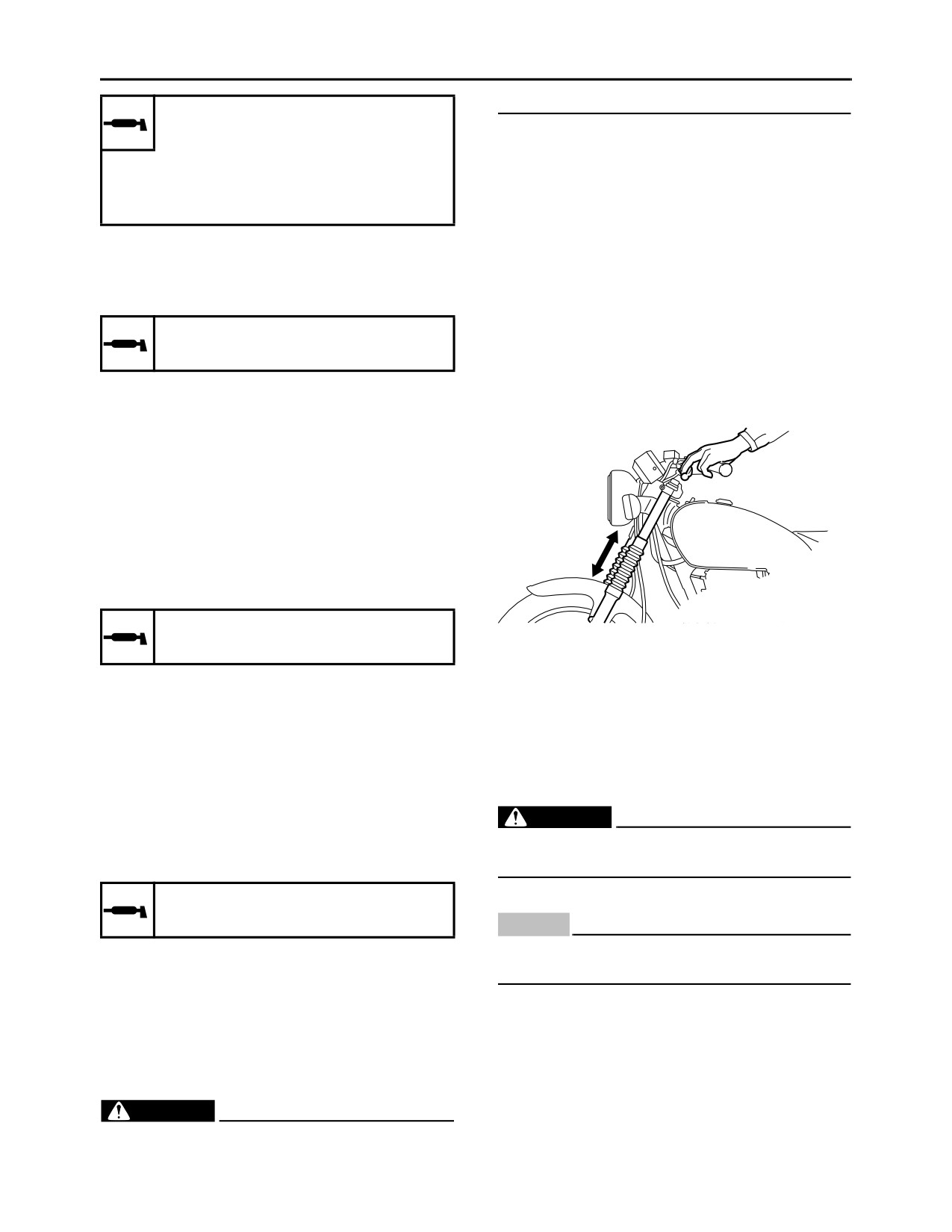
3. Check:
ed correctly.
• Fuel hose (pressure regulator-fuel tank) lo-
cation
2
TIP
Make sure that the fuel hose “1” is located (be-
low the frame), as shown.
1
1
3
1
4. Install:
• Fuel tank
Refer to “FUEL TANK” on page 6-1.
• Side cover (left)
• Seat
3-4
PERIODIC MAINTENANCE
Refer to “GENERAL CHASSIS” on page 4-1.
plug and gasket surface.
EAS20690
8. Connect:
CHECKING THE SPARK PLUG
• Spark plug cap
1. Remove:
EAS20520
• Spark plug cap
ADJUSTING THE VALVE CLEARANCE
2. Remove:
The following procedure applies to all of the
• Spark plug
valves.
ECA13330
NOTICE
TIP
• Valve clearance adjustment should be made
Before removing the spark plug, blow away
on a cold engine, at room temperature.
any dirt accumulated in the spark plug well
• When the valve clearance is to be measured or
with compressed air to prevent it from falling
adjusted, the piston must be at top dead center
into the cylinder.
(TDC) on the compression stroke.
3.
Check:
1.
Remove:
• Spark plug type
• Seat
Incorrect Change.
Refer to “GENERAL CHASSIS” on page 4-1.
Manufacturer/model
• Fuel tank
NGK/BPR6ES
Refer to “FUEL TANK” on page 6-1.
• Spark plug cap
4.
Check:
• Spark plug
• Electrode “1”
• Exhaust tappet cover “1”
Damage/wear Replace the spark plug.
• Intake tappet cover “2”
• Insulator “2”
Refer to “CYLINDER HEAD” on page 5-7.
Abnormal color Replace the spark plug.
Normal color is medium-to-light tan.
2
5.
Clean:
• Spark plug
1
(with a spark plug cleaner or wire brush)
6.
Measure:
• Spark plug gap “a”
Out of specification Regap.
Spark plug gap
0.7-0.8 mm (0.028-0.031 in)
2.
Remove:
• Crankcase cover (left)
Refer to “GENERATOR” on page 5-47.
3.
Measure:
• Valve clearance
Out of specification Adjust.
Valve clearance (cold)
Intake
0.07-0.12 mm (0.0028-0.0047 in)
Exhaust
0.12-0.17 mm (0.0047-0.0067 in)
7.
Install:
• Spark plug
▼▼▼▼▼▼▼▼▼▼▼▼▼▼▼▼▼▼▼▼▼▼▼▼▼▼▼▼▼▼▼▼
Spark plug
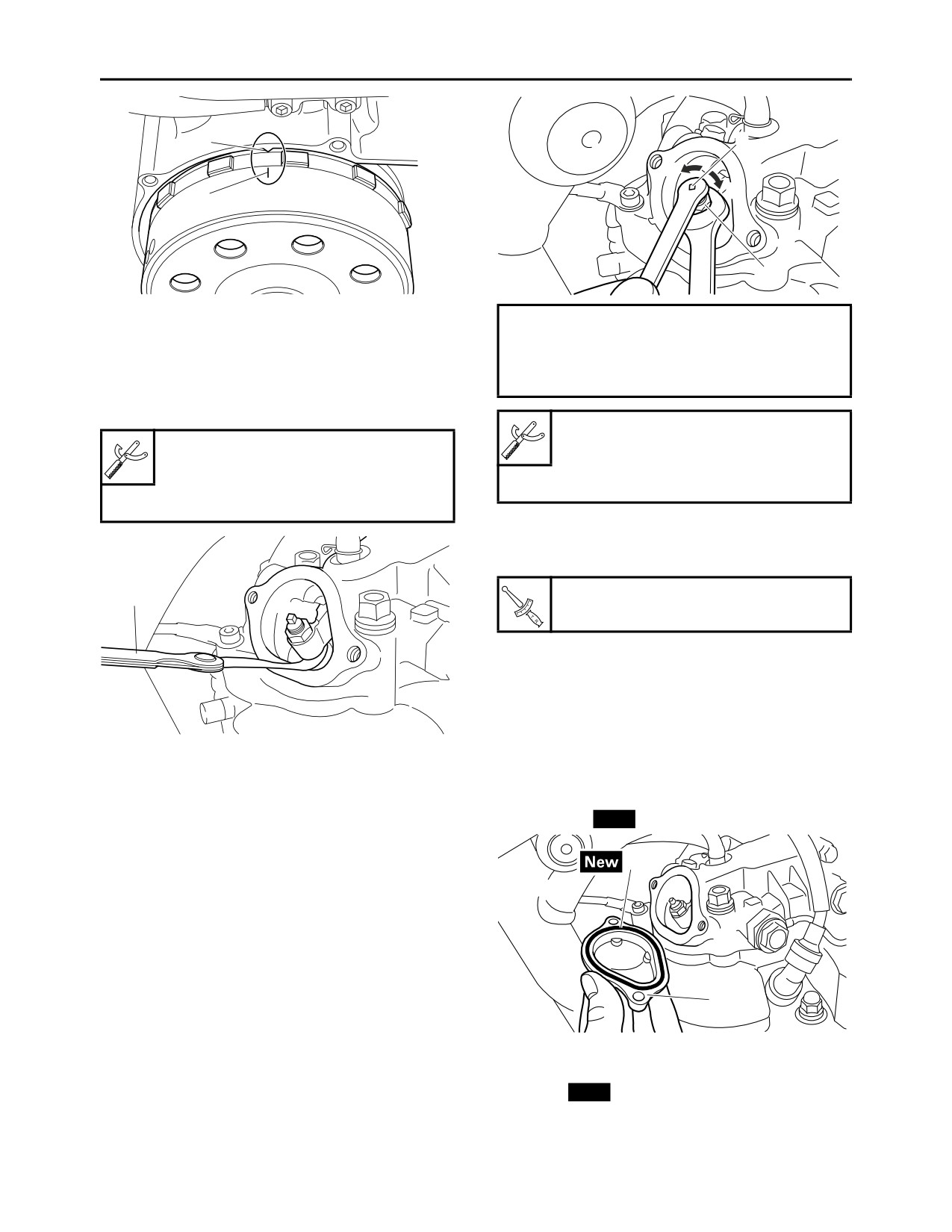
a. Turn the crankshaft counterclockwise.
25 Nm (2.5 m·kgf, 18 ft·lbf)
b. When the piston is on the compression
stroke, align AC magneto “T” mark “a” with
TIP
crankcase alignment mark “b”. (TDC)
Before installing the spark plug, clean the spark
3-5
PERIODIC MAINTENANCE
b
2
a
a
b
1
c. A position where the AC magneto “T” mark
Direction “a”
matches the crankcase alignment mark is the
Valve clearance is increased.
compression top dead center (TDC).
Direction “b”
d. Measure the valve clearance with a thickness
Valve clearance is decreased.
gauge “1”.
Out of specification Adjust.
Tappet adjusting tool (4 mm)
Thickness gauge
90890-04133
90890-03180
Six piece tappet set
Feeler gauge set
YM-A5970
YU-26900-9
• Hold the adjusting screw to prevent it from
moving and tighten the locknut to specifica-
tion.
Locknut
1
27 Nm (2.7 m·kgf, 20 ft·lbf)
d. Measure the valve clearance again.
e. If the valve clearance is still out of specifica-
tion, repeat all of the valve clearance adjust-
ment steps until the specified clearance is
obtained.
▲▲▲▲▲▲▲▲▲▲▲▲▲▲▲▲▲▲▲▲▲▲▲▲▲▲▲▲▲▲▲▲
▲▲▲▲▲▲▲▲▲▲▲▲▲▲▲▲▲▲▲▲▲▲▲▲▲▲▲▲▲▲▲▲
4. Adjust:
5. Install:
• Valve clearance
• Exhaust tappet cover “1”
▼▼▼▼▼▼▼▼▼▼▼▼▼▼▼▼▼▼▼▼▼▼▼▼▼▼▼▼▼▼▼▼
• O-ring “2”
New
a. Loosen the locknut “1”.
b. Insert a thickness gauge between the end of
2
the adjusting screw and the valve stem end.
c. Turn the adjusting screw “2” in direction “a” or
“b” until the specified valve clearance is ob-
tained.
1
6. Install:
• Intake tappet cover
• O-ring
New
• Spark plug
• Spark plug cap
• Crankcase cover (left)
3-6
PERIODIC MAINTENANCE
Refer to “GENERATOR” on page 5-47.
Engine idling speed
• Fuel tank
1200-1400 r/min
Refer to “FUEL TANK” on page 6-1.
• Seat
EAS21020
Refer to “GENERAL CHASSIS” on page 4-1.
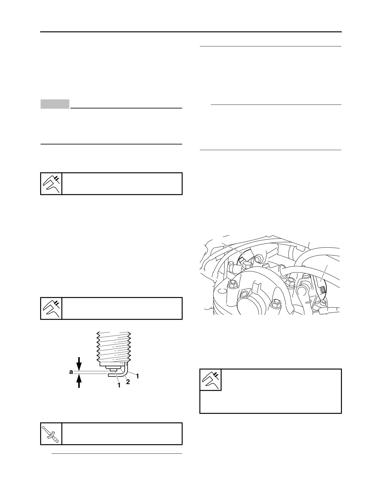
CHECKING THE THROTTLE BODY JOINT
7. Adjust:
1. Remove:
• Decompression lever free play
• Throttle body
Refer to “ADJUSTING THE DECOMPRES-
Refer to “THROTTLE BODY” on page 6-10.
SION LEVER FREE PLAY” on page 3-10.
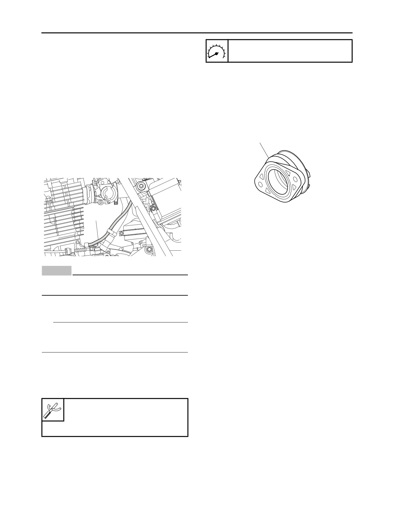
2. Check:
EAS21070
• Throttle body joint “1”
CHECKING THE CRANKCASE BREATHER
Cracks/damage Replace.
HOSE
1
1. Check:
• Crankcase breather hose “1”
Cracks/damage Replace.
Loose connection Connect properly.
1
3. Install:
• Throttle body
Refer to “THROTTLE BODY” on page 6-10.
EAS21081
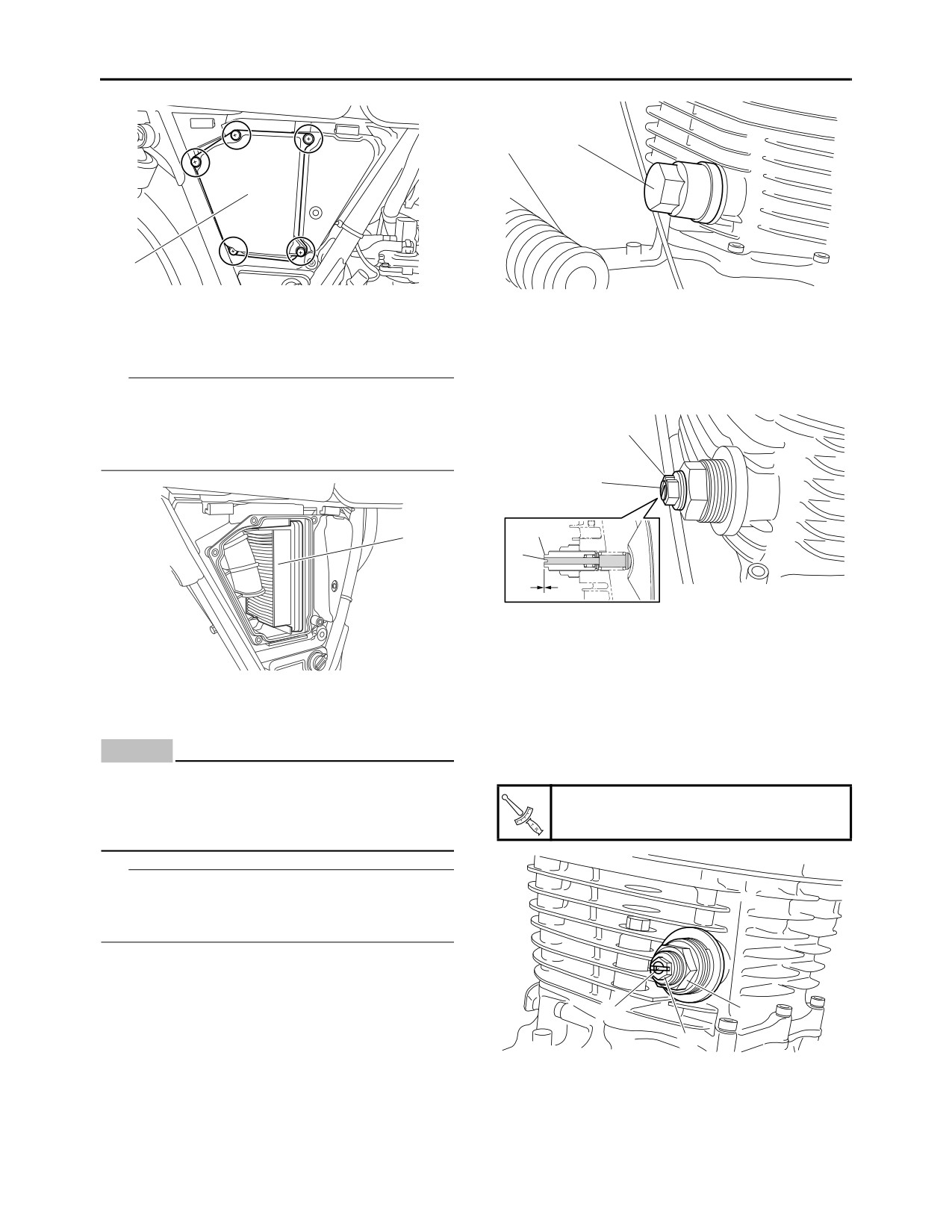
CHECKING THE EXHAUST SYSTEM
ECA13450
The following procedure applies to the exhaust
NOTICE
pipe and gasket.
Make sure the crankcase breather hose is
1. Remove:
routed correctly.
• Seat
Refer to “GENERAL CHASSIS” on page 4-1.
EAS2RD1006
• Fuel tank
CHECKING THE ENGINE IDLING SPEED
Refer to “FUEL TANK” on page 6-1.
TIP
2. Check:
Prior to checking the engine idling speed, the air
• Exhaust pipe “1”
filter element should be clean, and the engine
• Muffler “2”
should have adequate compression.
Cracks/damage Replace.
1. Start the engine and let it warm up for several
• Gasket “3”
minutes.
Exhaust gas leaks Replace the gasket.
2. Install:
• Digital tachometer
(To the spark plug lead)
Digital tachometer
90890-06760
Digital tachometer
YU-39951-B
3. Measure:
• Engine idling speed
Out of specification Replace the throttle
body.
3-7
PERIODIC MAINTENANCE
4. Install:
• Fuel tank
Refer to “FUEL TANK” on page 6-1.
• Seat
Refer to “GENERAL CHASSIS” on page 4-1.
2
EAS21090
CHECKING THE CANISTER (for California
only)
1. Check:
3
• Canister
• Canister purge hose
• Fuel tank breather hose
3
Cracks/damage Replace.
EAS2RD1009
CHECKING THE AIR INDUCTION SYSTEM
1
1. Check:
• Air induction system
Refer to “CHECKING THE AIR INDUCTION
SYSTEM” on page 6-18.
EAS2RD1008
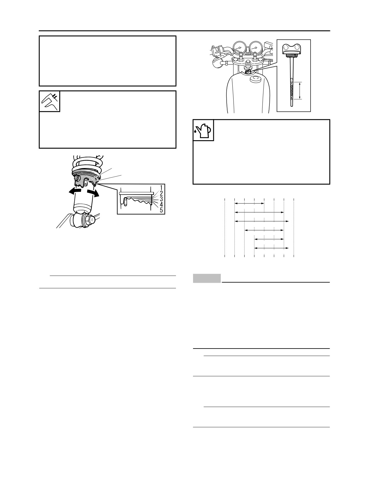
3. Check:
CHECKING THE OIL SEPARATOR
• Tightening torque
1. Check:
Exhaust pipe nut “1”
• Oil separator “1”
18 Nm (1.8 m·kgf, 13 ft·lbf)
Cracks/damage Replace.
Exhaust pipe and frame bolt “2”
Loose connections Tighten the clamp
23 Nm (2.3 m·kgf, 17 ft·lbf)
screw “2”.
Muffler joint bolt “3”
20 Nm (2.0 m·kgf, 14 ft·lbf)
Muffler bracket and frame bolt “4”
1
60 Nm (6.0 m·kgf, 43 ft·lbf)
Muffler and frame bracket bolt “5”
20 Nm (2.0 m·kgf, 14 ft·lbf)
2
5
EAS20961
REPLACING THE AIR FILTER ELEMENT
4
1. Remove:
• Side cover (right)
Refer to “GENERAL CHASSIS” on page 4-1.
3
2. Remove:
• Air filter case cover “1”
2
1
3-8
PERIODIC MAINTENANCE
1
1
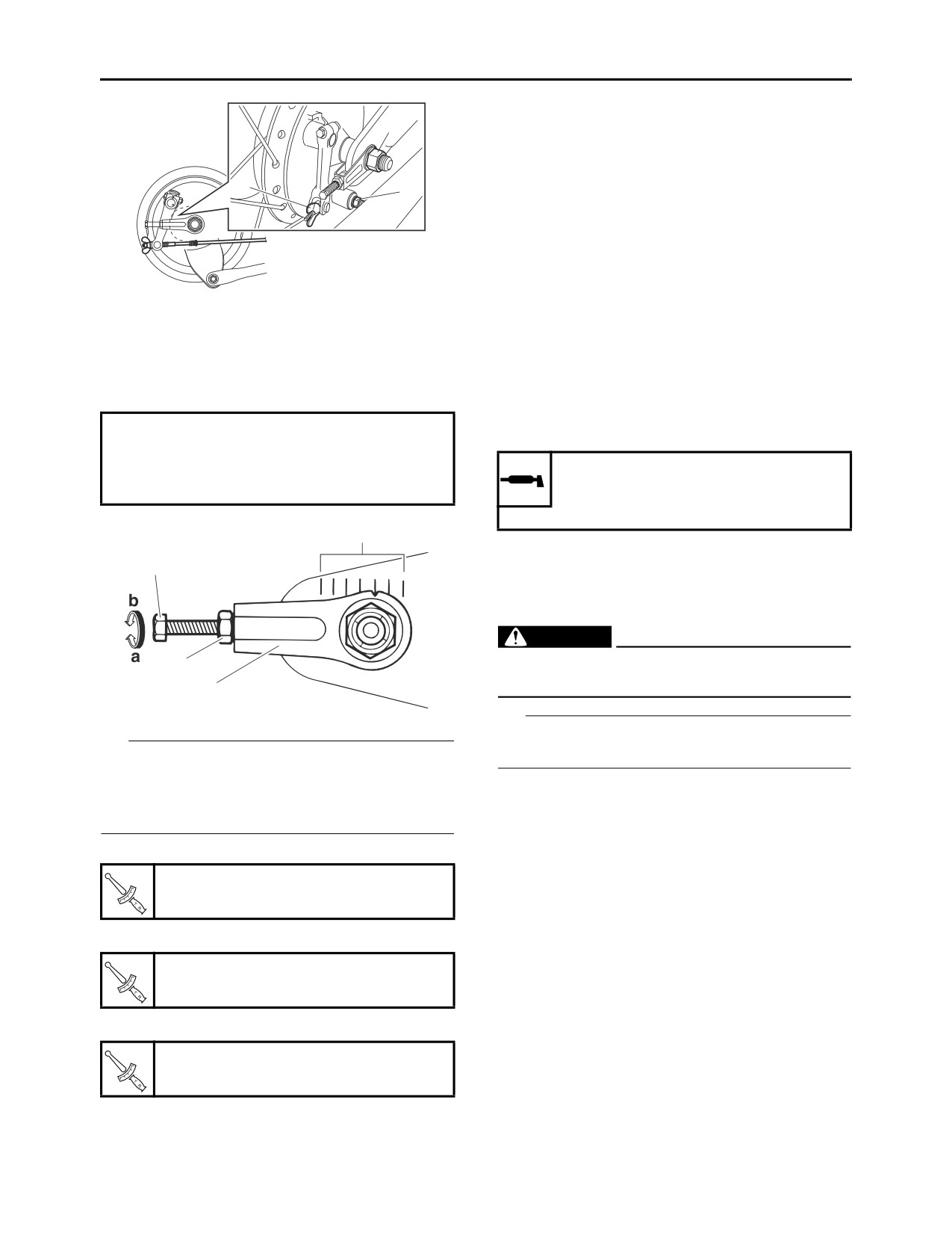
3. Check:
2. Check:
• Air filter element “1”
• Rod “1”
Dirt/damage Replace.
Check if the rod end “1” is flush with the ad-
TIP
juster end “2”.
• Replace the air filter element every 19000 km
Not flush Adjust.
(12000 mi) of operation.
2
• The air filter needs more frequent service if you
are riding in unusually wet or dusty areas.
1
2
1
1
3. Adjust:
• Timing chain tension
▼▼▼▼▼▼▼▼▼▼▼▼▼▼▼▼▼▼▼▼▼▼▼▼▼▼▼▼▼▼▼▼
a. Loosen the timing chain tensioner locknut “1”.
4. Install:
b. Turn the adjuster “2” in or out until the rod end
• Air filter case cover
ECA2RD1018
“3” is flush with the adjuster end “2”.
NOTICE
c. Tighten the timing chain tensioner locknut
“1”.
Never operate the engine without the air filter
element installed. Failure to install the air fil-
Timing chain tensioner locknut
ter element may cause rapid wear of engine
38 Nm (3.8 m·kgf, 27 ft·lbf)
parts and may damage the engine.
TIP
When installing the air filter element into the air
filter case cover, make sure that the sealing sur-
faces are aligned to prevent any air leaks.
5. Install:
• Side cover (right)
Refer to “GENERAL CHASSIS” on page 4-1.
3
1
EAS2RD1011
CHECKING THE TIMING CHAIN TENSIONER
2
1. Remove:
▲▲▲▲▲▲▲▲▲▲▲▲▲▲▲▲▲▲▲▲▲▲▲▲▲▲▲▲▲▲▲▲
• Timing chain tensioner cap “1”
4. Install:
• Timing chain tensioner cap
3-9
PERIODIC MAINTENANCE
EAS2RD1007
Timing chain tensioner cap
ADJUSTING THE DECOMPRESSION LEVER
18 Nm (1.8 m·kgf, 13 ft·lbf)
FREE PLAY
1. Fully turn the handle to the left.
EAS20870
2. Remove:
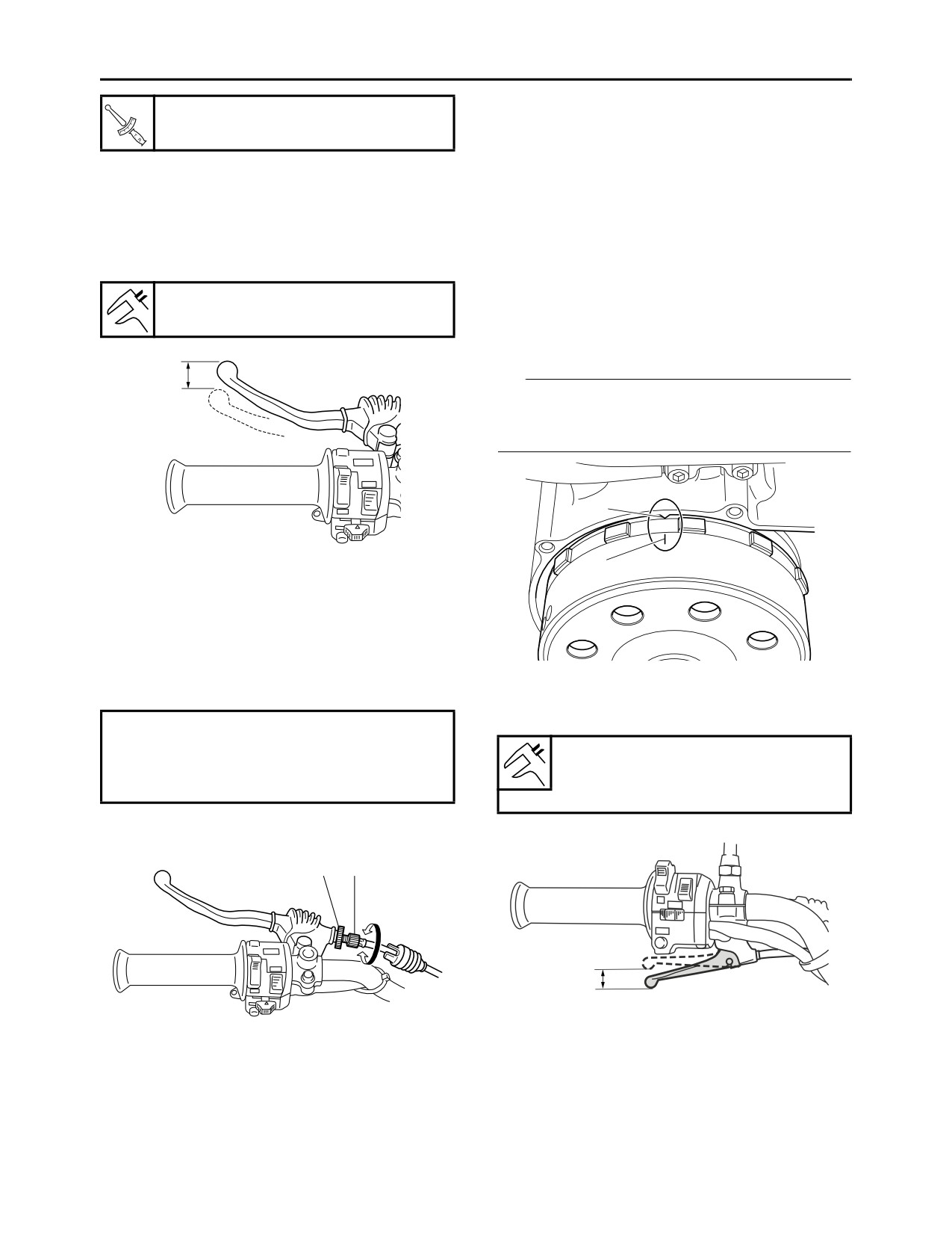
ADJUSTING THE CLUTCH LEVER FREE
• Spark plug cap
PLAY
• Spark plug
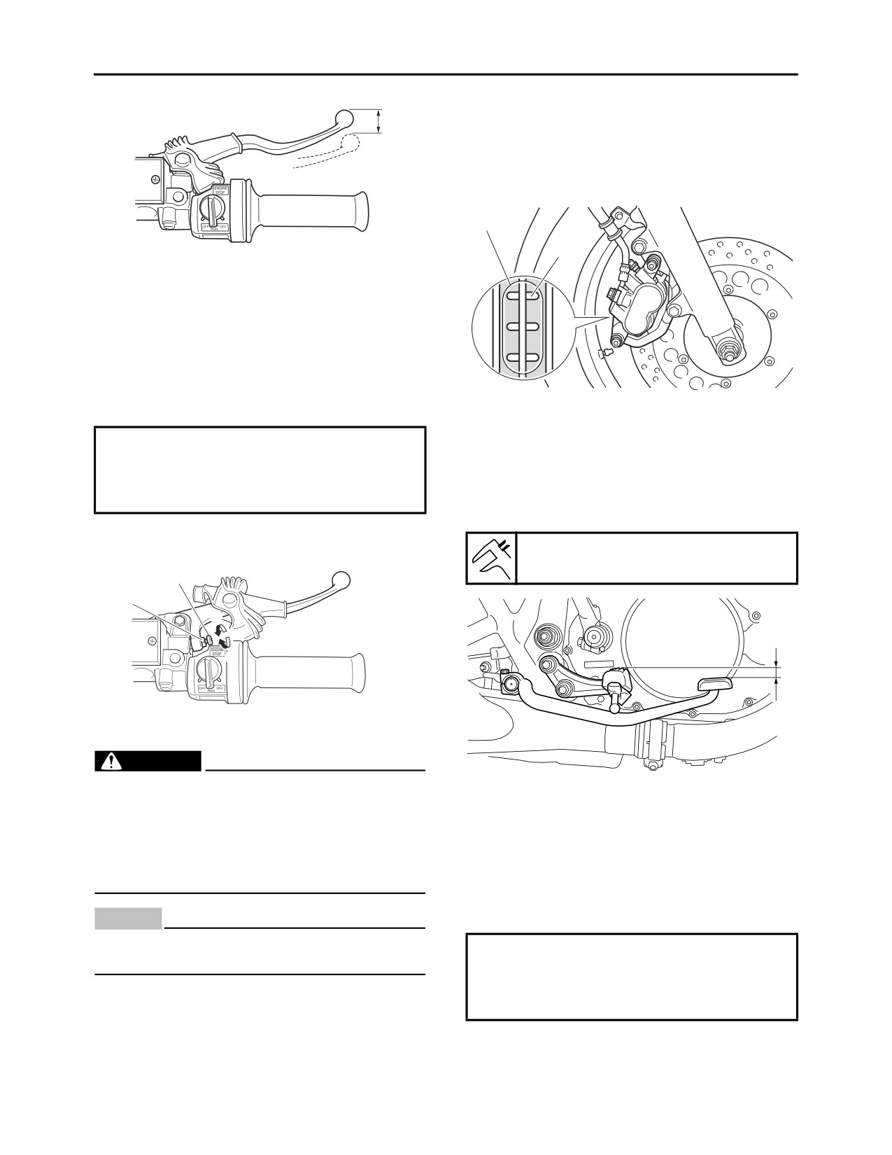
1. Check:
3. Remove:
• Clutch lever free play “a”
• Crankcase cover (left)
Out of specification Adjust.
Refer to “GENERATOR” on page 5-47.
4. Turn the AC magneto counterclockwise and
Clutch lever free play
5.0-10.0 mm (0.20-0.39 in)
align the “T” mark “a” of the AC magneto with
the matching mark “b” of the crankcase at
compression top dead center.
a
TIP
A position where the AC magneto “T” mark
matches the crankcase matching mark is the
compression top dead center (TDC).
b
a
2. Adjust:
• Clutch lever free play
▼▼▼▼▼▼▼▼▼▼▼▼▼▼▼▼▼▼▼▼▼▼▼▼▼▼▼▼▼▼▼▼
a. Loosen the locknut “1”.
b. Turn the adjusting bolt “2” in direction “a” or
“b” until the specified clutch lever free play is
5. Check:
obtained.
• Decompression lever free play “a”
Out of specification Adjust.
Direction “a”
Clutch lever free play is increased.
Decompression lever free play
Direction “b”
(decompression lever end)
Clutch lever free play is decreased.
5.0-10.0 mm (0.20-0.39 in)
c. Tighten the locknut “1”.
1
2
a
b
a
6. Adjust:
▲▲▲▲▲▲▲▲▲▲▲▲▲▲▲▲▲▲▲▲▲▲▲▲▲▲▲▲▲▲▲▲
• Decompression lever free play
▼▼▼▼▼▼▼▼▼▼▼▼▼▼▼▼▼▼▼▼▼▼▼▼▼▼▼▼▼▼▼▼
a. Loosen the locknut “1”.
b. Turn the adjusting nut “2” in direction “a” or “b”
until specified decompression lever free play
3-10
PERIODIC MAINTENANCE
is obtained.
Specified brake fluid
DOT 4
Direction “a”
Decompression lever free play is in-
creased.
Direction “b”
Decompression lever free play is de-
creased.
a
1
b
EWA13090
WARNING
a
• Use only the designated brake fluid. Other
2
brake fluids may cause the rubber seals to
deteriorate, causing leakage and poor
c. Tighten the locknut.
brake performance.
▲▲▲▲▲▲▲▲▲▲▲▲▲▲▲▲▲▲▲▲▲▲▲▲▲▲▲▲▲▲▲▲
• Refill with the same type of brake fluid that
is already in the system. Mixing brake fluids
7. Install:
may result in a harmful chemical reaction,
• Crankcase cover (left)
leading to poor brake performance.
Refer to “GENERATOR” on page 5-47.
• When refilling, be careful that water does
8. Install:
not enter the brake fluid reservoir. Water
• Spark plug
will significantly lower the boiling point of
• Spark plug cap
the brake fluid and could cause vapor lock.
EAS2RD1020
ECA13540
CHECKING THE BRAKE OPERATION
NOTICE
1. Check:
Brake fluid may damage painted surfaces
• Brake operation
and plastic parts. Therefore, always clean up
Brake not working properly Check the
any spilt brake fluid immediately.
brake system.
Refer to “FRONT BRAKE” on page 4-17 and
TIP
“REAR BRAKE” on page 4-30.
In order to ensure a correct reading of the brake
TIP
fluid level, make sure the top of the brake fluid
Drive on the dry road, operate the front and rear
reservoir is horizontal.
brakes separately and check to see if the brakes
are operating properly.
EAS21170
ADJUSTING THE FRONT DISC BRAKE
EAS21240
1. Check:
CHECKING THE BRAKE FLUID LEVEL
• Brake lever free play “a”
1. Stand the vehicle on a level surface.
Out of specification Adjust.
TIP
Front brake lever free play
• Place the vehicle on a suitable stand.
5.0-8.0 mm (0.20-0.31 in)
• Make sure the vehicle is upright.
2. Check:
• Brake fluid level
Below the minimum level mark “a” Add the
specified brake fluid to the proper level.
3-11
PERIODIC MAINTENANCE
1. Operate the brake.
2. Check:
a
• Front brake pad “1”
Wear indicator grooves “2” almost disap-
peared Replace the brake pads as a set.
Refer to “FRONT BRAKE” on page 4-17.
1
2
2. Adjust:
• Brake lever free play
▼▼▼▼▼▼▼▼▼▼▼▼▼▼▼▼▼▼▼▼▼▼▼▼▼▼▼▼▼▼▼▼
a. Loosen the locknut “1”.
b. Turn the adjusting screw “2” in direction “a” or
“b” until the specified brake lever free play is
EAS21220
obtained.
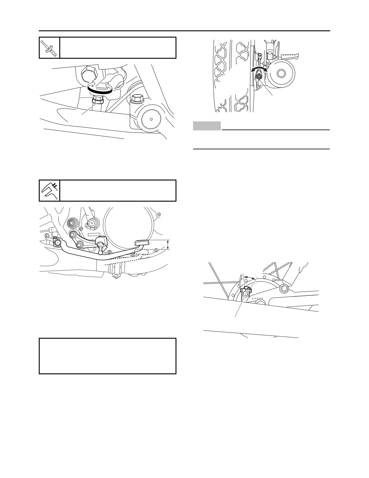
ADJUSTING THE REAR DRUM BRAKE
Direction “a”
1. Check:
Brake lever free play is increased.
• Brake pedal position
Direction “b”
(distance “a” from the top of the rider footrest
Brake lever free play is decreased.
to the top of the brake pedal)
Out of specification Adjust.
c. Tighten the locknut “1”.
Brake pedal position
20.0 mm (0.79 in)
2
1
a
b
a
EWA13050
WARNING
A soft or spongy feeling in the brake lever
2. Adjust:
can indicate the presence of air in the brake
• Brake pedal position
system. Before the vehicle is operated, the
air must be removed by bleeding the brake
▼▼▼▼▼▼▼▼▼▼▼▼▼▼▼▼▼▼▼▼▼▼▼▼▼▼▼▼▼▼▼▼
system. Air in the brake system will consid-
a. Loosen the locknut “1”.
erably reduce braking performance.
b. Turn the adjusting bolt “2” in direction “a” or
“b” until the specified brake pedal position is
ECA13490
obtained.
NOTICE
After adjusting the brake lever position,
Direction “a”
make sure there is no brake drag.
Brake pedal is lowered.
Direction “b”
▲▲▲▲▲▲▲▲▲▲▲▲▲▲▲▲▲▲▲▲▲▲▲▲▲▲▲▲▲▲▲▲
Brake pedal is raised.
EAS21250
CHECKING THE FRONT BRAKE PADS
c. Tighten the locknut “1” to specification.
The following procedure applies to all of the
brake pads.
3-12
PERIODIC MAINTENANCE
Locknut
7 Nm (0.7 m·kgf, 5.1 ft·lbf)
a
b
b
a
2
1
1
ECA13520
NOTICE
After adjusting the brake pedal position and
free play, make sure there is no brake drag.
▲▲▲▲▲▲▲▲▲▲▲▲▲▲▲▲▲▲▲▲▲▲▲▲▲▲▲▲▲▲▲▲
▲▲▲▲▲▲▲▲▲▲▲▲▲▲▲▲▲▲▲▲▲▲▲▲▲▲▲▲▲▲▲▲
3. Check:
• Brake pedal free play “a”
5. Adjust:
Out of specification Adjust.
• Rear brake light switch
Refer to “ADJUSTING THE REAR BRAKE
Brake pedal free play
LIGHT SWITCH” on page 3-23.
20.0-30.0 mm (0.79-1.18 in)
EAS21310
CHECKING THE REAR BRAKE SHOES
1. Operate the brake.
2. Check:
• Brake shoe wear indicator “1”
Reaches the wear limit line “2” Replace the
a
brake shoes as a set.
Refer to “REAR BRAKE” on page 4-30.
2
4. Adjust:
• Brake pedal free play
▼▼▼▼▼▼▼▼▼▼▼▼▼▼▼▼▼▼▼▼▼▼▼▼▼▼▼▼▼▼▼▼
a. Turn the adjusting nut “1” in direction “a” or “b”
1
until the specified brake pedal free play is ob-
tained.
Direction “a”
EAS21270
Brake pedal free play is increased.
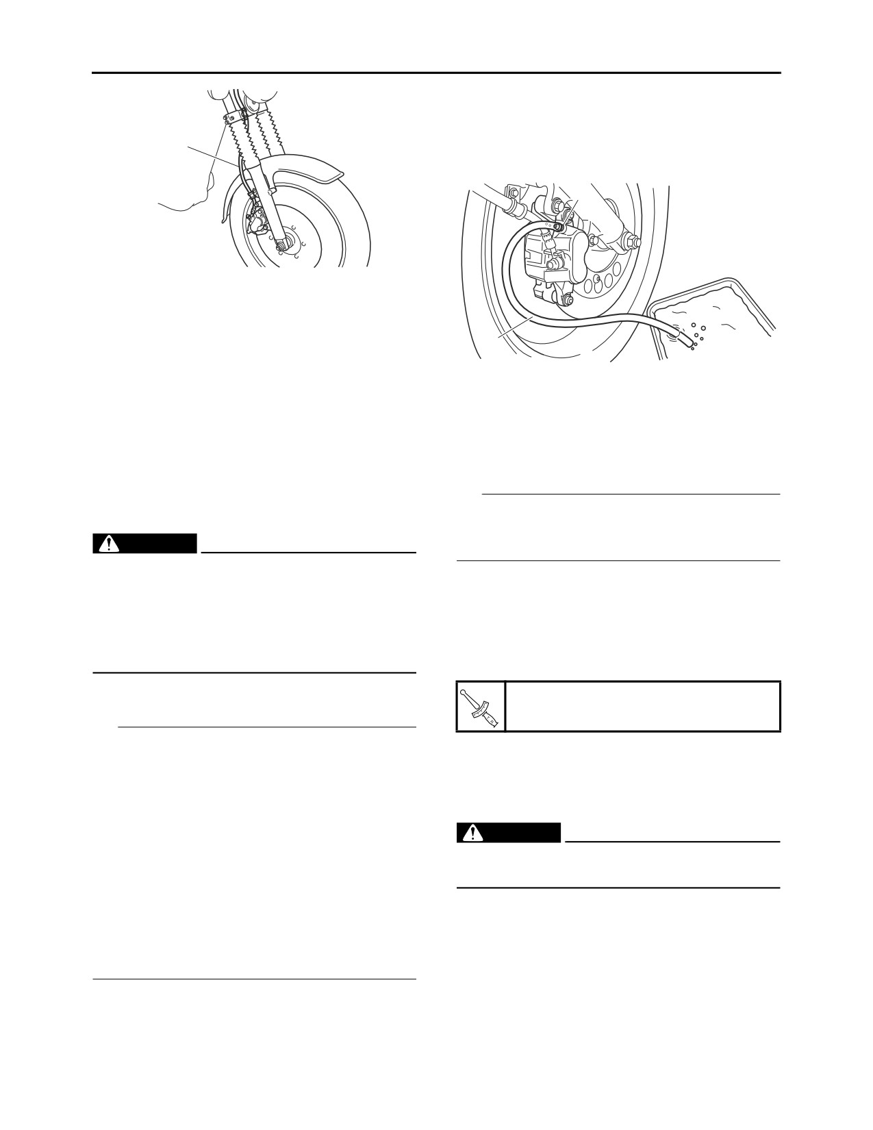
CHECKING THE FRONT BRAKE HOSE
Direction “b”
1. Check:
Brake pedal free play is decreased.
• Brake hose “1”
Cracks/damage/wear Replace.
3-13
PERIODIC MAINTENANCE
with the specified brake fluid.
b. Install the brake master cylinder reservoir di-
aphragm.
1
c. Connect a clear plastic hose “1” tightly to the
bleed screw “2”.
2
2. Check:
• Brake hose clamp
Loose Tighten the clamp bolt.
3. Hold the vehicle upright and apply the front
1
brake several times.
4. Check:
d. Place the other end of the hose into a con-
• Brake hose
tainer.
Brake fluid leakage Replace the damaged
e. Slowly apply the brake lever several times.
hose.
f. Fully pull the brake lever and hold it in posi-
Refer to “FRONT BRAKE” on page 4-17.
tion.
g. Loosen the bleed screw.
EAS21340
TIP
BLEEDING THE HYDRAULIC BRAKE
Loosening the bleed screw will release the pres-
SYSTEM
EWA13100
sure and cause the brake lever to contact the
WARNING
throttle grip.
Bleed the hydraulic brake system whenever:
h. Tighten the bleed screw and then release the
• the system is disassembled.
brake lever.
• a brake hose is loosened, disconnected or
i. Repeat steps (e) to (h) until all of the air bub-
replaced.
bles have disappeared from the brake fluid in
• the brake fluid level is very low.
the plastic hose.
• brake operation is faulty.
j. Tighten the bleed screw to specification.
1. Remove:
Bleed screw
• Reservoir cap
6 Nm (0.6 m·kgf, 4.3 ft·lbf)
TIP
• Be careful not to spill any brake fluid or allow
k. Fill the brake fluid reservoir to the proper level
the brake master cylinder reservoir or brake
with the specified brake fluid.
fluid reservoir to overflow.
Refer to “CHECKING THE BRAKE FLUID
• When bleeding the hydraulic brake system,
LEVEL” on page 3-11.
make sure there is always enough brake fluid
EWA13110
before applying the brake. Ignoring this pre-
WARNING
caution could allow air to enter the hydraulic
After bleeding the hydraulic brake system,
brake system, considerably lengthening the
check the brake operation.
bleeding procedure.
▲▲▲▲▲▲▲▲▲▲▲▲▲▲▲▲▲▲▲▲▲▲▲▲▲▲▲▲▲▲▲▲
• If bleeding is difficult, it may be necessary to let
the brake fluid settle for a few hours. Repeat
EAS21670
the bleeding procedure when the tiny bubbles
CHECKING THE WHEELS
in the hose have disappeared.
The following procedure applies to both of the
wheels.
2. Bleed:
1. Check:
• Hydraulic brake system
• Wheel
▼▼▼▼▼▼▼▼▼▼▼▼▼▼▼▼▼▼▼▼▼▼▼▼▼▼▼▼▼▼▼▼
Damage/out-of-round Replace.
a. Fill the brake fluid reservoir to the proper level
3-14
PERIODIC MAINTENANCE
EWA13260
WARNING
Never attempt to make any repairs to the
1
wheel.
TIP
After a tire or wheel has been changed or re-
placed, always balance the wheel.
EAS21681
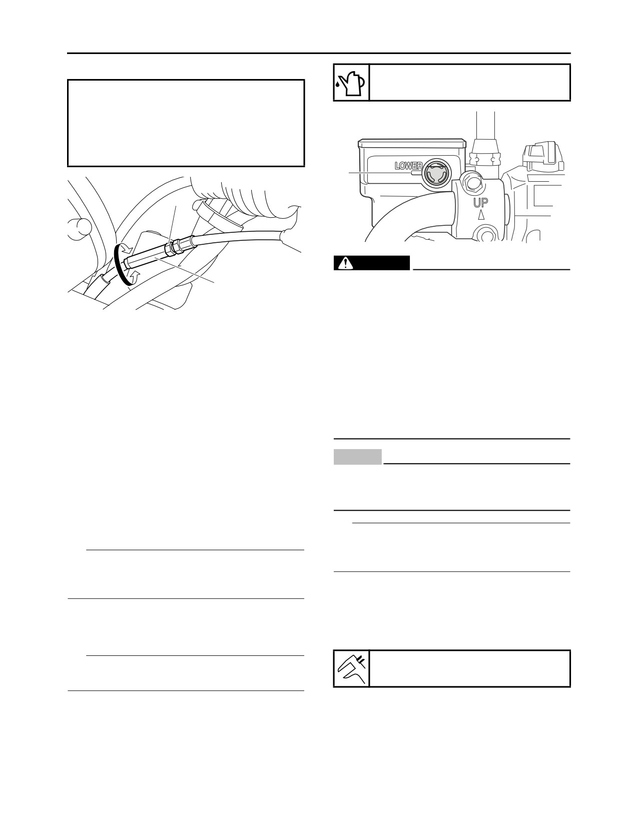
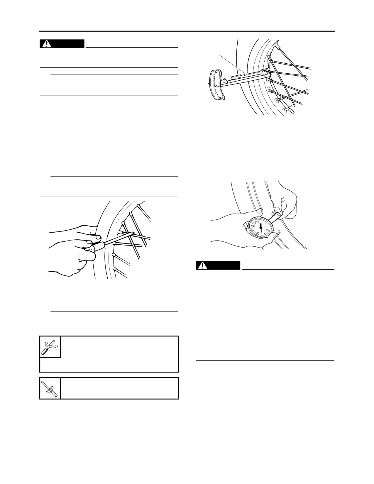
CHECKING AND TIGHTENING THE SPOKES
The following procedure applies to all of the
EAS21650
spokes.
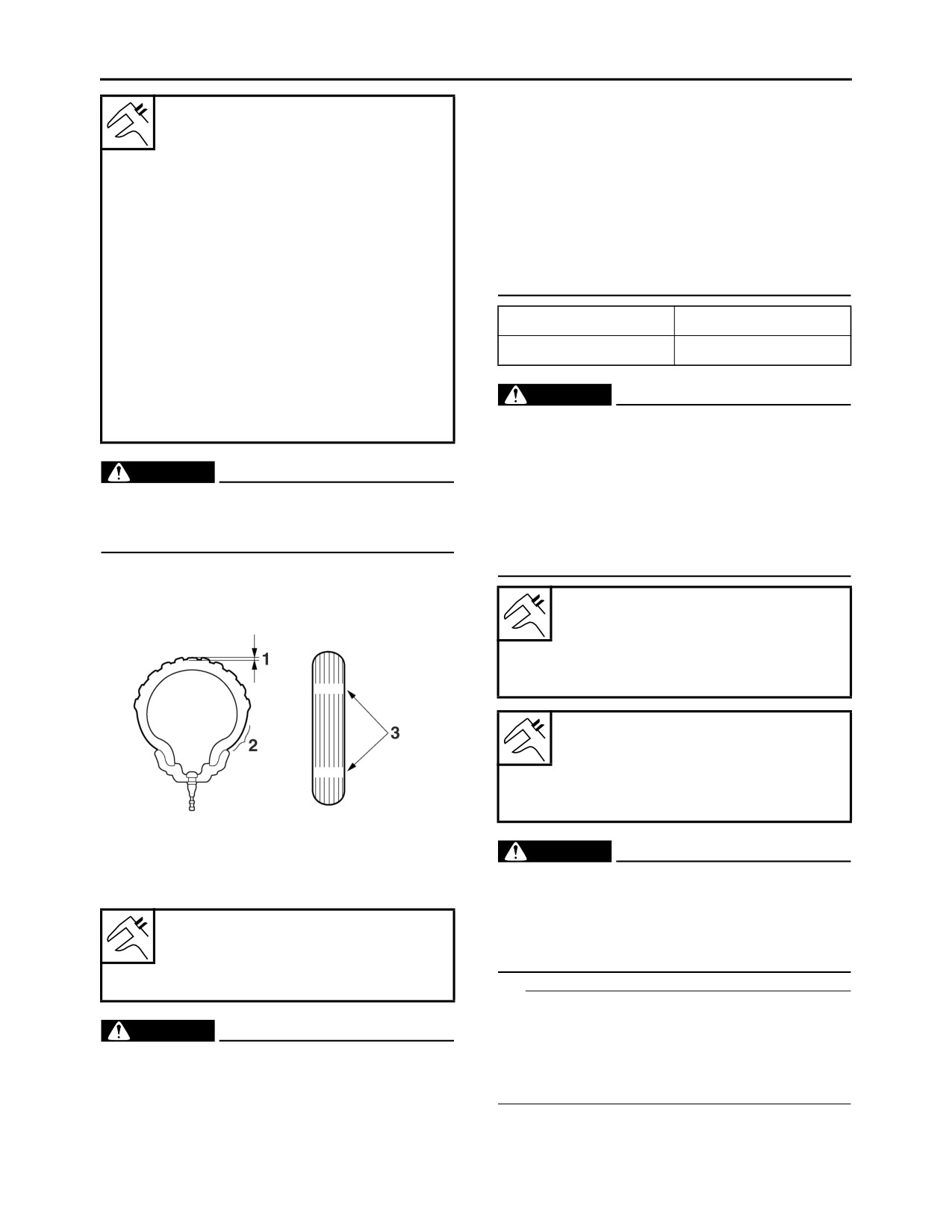
CHECKING THE TIRES
1. Check:
The following procedure applies to both of the
• Spoke
tires.
Bends/damage Replace.
1. Check:
Loose Tighten.
• Tire pressure
Tap the spokes with a screwdriver.
Out of specification Regulate.
TIP
A tight spoke will emit a clear, ringing tone; a
loose spoke will sound flat.
EWA1
3180
WARNING
•T
he tire pressure should only be checked
and regulated when the tire temperature
2. Tighten:
equals the ambient air temperature.
• Spoke
• The tire pressure and the suspension must
(with a spoke nipple wrench “1”)
be adjusted according to the total weight
TIP
(including cargo, rider, passenger and ac-
Be sure to tighten the spokes before and after
cessories) and the anticipated riding
break-in.
speed.
• Operation of an overloaded vehicle could
Spoke nipple wrench (8-9)
cause tire damage, an accident or an injury.
90890-01522
NEVER OVERLOAD THE VEHICLE.
Spoke nipple wrench (8-9)
YM-01522
Spoke
3.0 Nm (0.30 m·kgf, 2.2 ft·lbf)
3-15
PERIODIC MAINTENANCE
• Always replace a new tube tire and a new
Tire air pressure (measured on
tube as a set.
cold tires)
• To avoid pinching the tube, make sure the
Loading condition
wheel rim band and tube are centered in the
0-90 kg (0-198 lb)
wheel groove.
Front
• Patching a punctured tube is not recom-
175 kPa (1.75 kgf/cm², 25 psi)
Rear
mended. If it is absolutely necessary to do
200 kPa (2.00 kgf/cm², 29 psi)
so, use great care and replace the tube as
Loading condition
soon as possible with a good quality re-
90-150 kg (198-331 lb)
placement.
Front
200 kPa (2.00 kgf/cm², 29 psi)
Tube wheel
Tube tire only
Rear
Tubeless wheel
Tube or tubeless tire
225 kPa (2.25 kgf/cm², 33 psi)
Maximum load
EWA14090
150 kg (331 lb)
WARNING
* Total weight of rider, passenger, cargo
After extensive tests, the tires listed below
and accessories
have been approved by Yamaha Motor Co.,
EWA13190
Ltd. for this model. The front and rear tires
WARNING
should always be by the same manufacturer
It is dangerous to ride with a worn-out tire.
and of the same design. No guarantee con-
When the tire tread reaches the wear limit, re-
cerning handling characteristics can be giv-
place the tire immediately.
en if a tire combination other than one
approved by Yamaha is used on this vehicle.
2. Check:
• Tire surfaces
Front tire
Damage/wear Replace the tire.
Size
90/100-18M/C 54S
Manufacturer/model
BRIDGESTONE/BT-45
Rear tire
Size
110/90-18M/C 61S
Manufacturer/model
BRIDGESTONE/BT-45
EWA13210
1. Tire tread depth
WARNING
2. Side wall
New tires have a relatively low grip on the
3. Wear indicator
road surface until they have been slightly
worn. Therefore, approximately
100 km
Wear limit (front)
should be traveled at normal speed before
1.0 mm (0.04 in)
any high-speed riding is done.
Wear limit (rear)
1.0 mm (0.04 in)
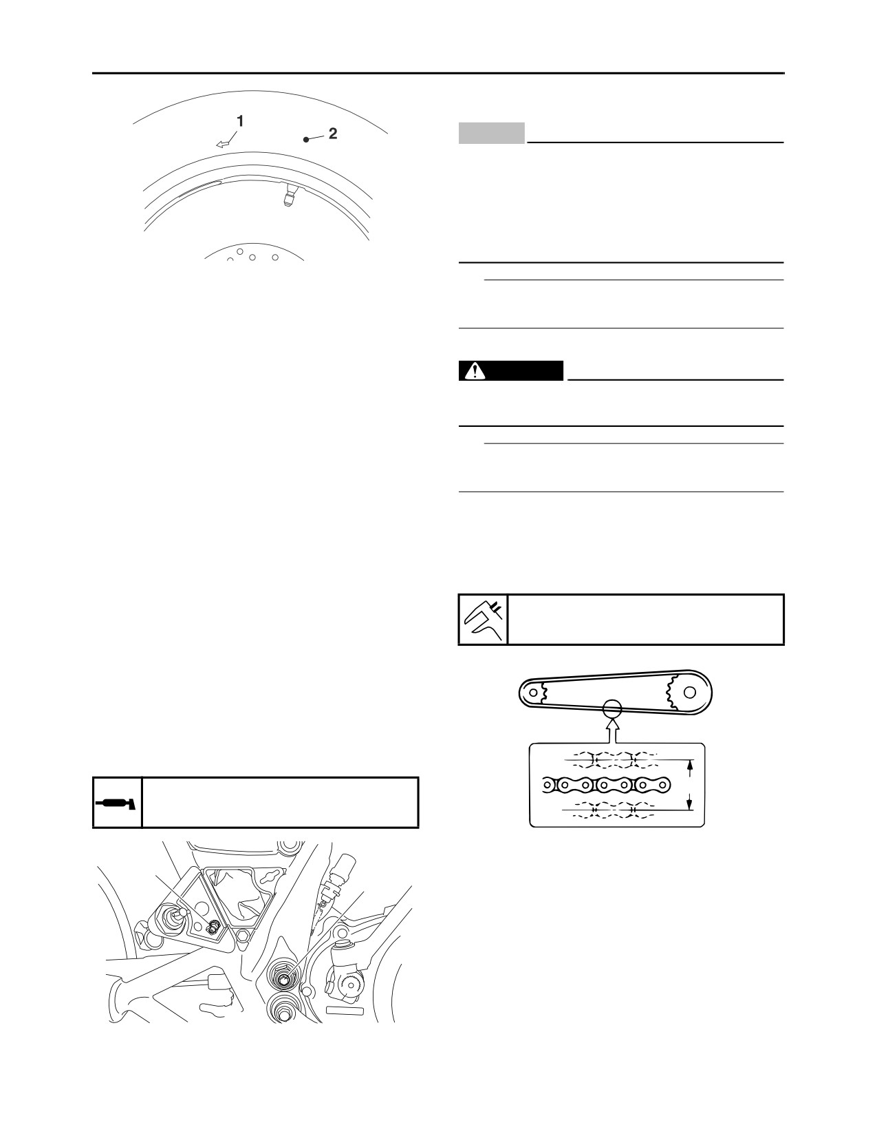
TIP
For tires with a direction of rotation mark “1”:
EWA14080
• Install the tire with the mark pointing in the di-
WARNING
rection of wheel rotation.
• Do not use a tubeless tire on a wheel de-
• Align the mark “2” with the valve installation
signed only for tube tires to avoid tire fail-
point.
ure and personal injury from sudden
deflation.
• When using a tube tire, be sure to install the
correct tube.
3-16
PERIODIC MAINTENANCE
EAS21390
ADJUSTING THE DRIVE CHAIN SLACK
ECA13550
NOTICE
A drive chain that is too tight will overload
the engine and other vital parts, and one that
is too loose can skip and damage the swing-
arm or cause an accident. Therefore, keep
the drive chain slack within the specified lim-
its.
TIP
EAS2RD1021
The drive chain slack must be checked at the
CHECKING THE WHEEL BEARINGS
tightest point on the chain.
The following procedure applies to all of the
wheel bearings.
1. Stand the vehicle on a level surface.
EWA13120
1. Check:
WARNING
• Wheel bearing
Refer to “CHECKING THE FRONT WHEEL”
Securely support the vehicle so that there is
on page 4-7 and “CHECKING THE REAR
no danger of it falling over.
WHEEL” on page 4-14.
TIP
EAS2RD1022
Place the vehicle on a suitable stand so that the
CHECKING THE SWINGARM OPERATION
rear wheel is elevated.
1. Check:
2. Move the rear wheel several times and find
• Swingarm operation
the tightest position of drive chain.
Swingarm not working properly Check the
3. Check:
swingarm.
• Drive chain slack “a”
Refer to “REAR SHOCK ABSORBER AS-
Out of specification Adjust.
SEMBLY AND SWINGARM” on page 4-48.
2. Check:
Drive chain slack
• Swingarm excessive play
30.0-40.0 mm (1.18-1.57 in)
Refer to “REAR SHOCK ABSORBER AS-
SEMBLY AND SWINGARM” on page 4-48.
EAS2RD1029
LUBRICATING THE SWINGARM
Remove the bolts “1” at both ends of the pivot
shaft and install the grease nipple “2” to the pivot
shaft before lubrication.
a
Recommended lubricant
Lithium-soap-based grease
4. Adjust:
2
• Drive chain slack
1
▼▼▼▼▼▼▼▼▼▼▼▼▼▼▼▼▼▼▼▼▼▼▼▼▼▼▼▼▼▼▼▼
a. Loosen wheel axle nut “1”.
b. Loosen the brake pedal free play adjusting
nut “2” and tension bar nut “3”.
3-17
PERIODIC MAINTENANCE
EAS21440
LUBRICATING THE DRIVE CHAIN
1
The drive chain consists of many interacting
parts. If the drive chain is not maintained proper-
ly, it will wear out quickly. Therefore, the drive
2
3
chain should be serviced, especially when the
vehicle is used in dusty areas.
This vehicle has a drive chain with small rubber
O-rings between each side plate. Steam clean-
ing, high-pressure washing, certain solvents,
and the use of a coarse brush can damage
c. Loosen the locknut “4” on each end of the
these O-rings. Therefore, use only kerosene to
swingarm.
clean the drive chain. Wipe the drive chain dry
d. Turn the adjusting bolt “5” on each end of the
and thoroughly lubricate it with engine oil or
swingarm in direction “a” or “b” until the spec-
chain lubricant that is suitable for O-ring chains.
ified drive chain slack is obtained.
Do not use any other lubricants on the drive
chain since they may contain solvents that could
Direction “a”
damage the O-rings.
Drive chain is tightened.
Direction “b”
Recommended lubricant
Drive chain is loosened.
Chain lubricant suitable for O-
ring chains
c
EAS21510
5
CHECKING AND ADJUSTING THE
STEERING HEAD
1. Stand the vehicle on a level surface.
EWA13120
WARNING
4
Securely support the vehicle so that there is
d
no danger of it falling over.
TIP
Place the vehicle on a suitable stand so that the
TIP
front wheel is elevated.
Using the alignment marks “c” on each end of
the swingarm, make sure that both drive chain
2. Check:
pullers “d” are in the same position for proper
• Steering head
wheel alignment.
Grasp the bottom of the front fork legs and
gently rock the front fork.
e. Tighten the wheel axle nut to specification.
Binding/looseness
Adjust the steering
Wheel axle nut
head.
129 Nm (12.9 m·kgf, 93 ft·lbf)
3. Remove:
• Upper bracket
f. Tighten the locknuts to specification.
Refer to “STEERING HEAD” on page 4-44.
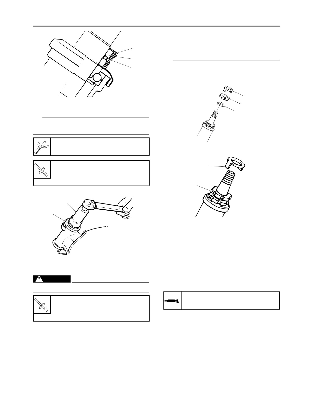
4. Adjust:
Locknut
16 Nm (1.6 m·kgf, 12 ft·lbf)
• Steering head
▼▼▼▼▼▼▼▼▼▼▼▼▼▼▼▼▼▼▼▼▼▼▼▼▼▼▼▼▼▼▼▼
g. Tighten the tension bar nut to specification.
a. Remove the lock washer “1”, upper ring nut
“2”, and rubber washer “3”.
Tension bar nut
19 Nm (1.9 m·kgf, 14 ft·lbf)
▲▲▲▲▲▲▲▲▲▲▲▲▲▲▲▲▲▲▲▲▲▲▲▲▲▲▲▲▲▲▲▲
3-18
PERIODIC MAINTENANCE
g. Finger tighten the upper ring nut, then align
the slots of both ring nuts. If necessary, hold
the lower ring nut and tighten the upper ring
1
nut until their slots are aligned.
2
TIP
3
Make sure the lock washer “3” tab “a” sit correct-
ly in the ring nut slots “b”.
3
b. Tighten the lower ring nut “4” to specification
2
with a steering nut wrench “5”.
1
TIP
Set the torque wrench at a right angle to the
steering nut wrench.
Steering nut wrench
90890-01385
Lower ring nut (initial tightening
a
torque)
38 Nm (3.8 m·kgf, 27 ft·lbf)
b
5
4
▲▲▲▲▲▲▲▲▲▲▲▲▲▲▲▲▲▲▲▲▲▲▲▲▲▲▲▲▲▲▲▲
5. Install:
• Upper bracket
Refer to “STEERING HEAD” on page 4-44.
354-017
EAS2RD1024
LUBRICATING THE STEERING HEAD
c. After fully loosening the lower ring nut, tighten
1. Lubricate:
it to specification with a steering nut wrench.
EWA13140
• Upper bearing
WARNING
• Lower bearing
Do not overtighten the lower ring nut.
• Bearing race
Recommended lubricant
Lower ring nut (final tightening
Lithium-soap-based grease
torque)
18 Nm (1.8 m·kgf, 13 ft·lbf)
EAS2RD1025
CHECKING THE CHASSIS FASTENERS
d. Check the steering head for looseness or
Make sure that all nuts, bolts, and screws are
binding by turning the front fork all the way in
properly tightened.
both directions. If any binding is felt, remove
Refer to “CHASSIS TIGHTENING TORQUES”
the lower bracket and check the upper and
on page 2-16.
lower bearings.
EAS21700
Refer to
“CHECKING THE STEERING
LUBRICATING THE LEVERS
HEAD” on page 4-46.
Lubricate the pivoting point and metal-to-metal
e. Install the rubber washer “1”.
moving parts of the levers.
f. Install the upper ring nut “2”.
3-19
PERIODIC MAINTENANCE
no danger of it falling over.
Recommended brake lever lubri-
cant
2. Check:
Silicone grease
• Inner tube
Recommended clutch lever lubri-
Damage/scratches Replace.
cant
• Front fork leg
Lithium-soap-based grease
Oil leaks between inner tube and outer tube
Replace the oil seal.
EAS21710
3. Hold the vehicle upright and apply the front
LUBRICATING THE PEDAL
brake.
Lubricate the pivoting point and metal-to-metal
4. Check:
moving parts of the pedal.
• Front fork operation
Recommended lubricant
Push down hard on the handlebar several
Lithium-soap-based grease
times and check if the front fork rebounds
smoothly.
EAS2RD1026
Rough movement Repair.
CHECKING THE SIDESTAND
Refer to “FRONT FORK” on page 4-37.
1. Check:
• Sidestand operation
Check that the sidestand moves smoothly.
Rough movement Repair or replace.
EAS21720
LUBRICATING THE SIDESTAND
Lubricate the pivoting point, metal-to-metal mov-
ing parts and spring contact point of the sides-
tand.
Recommended lubricant
EAS2RD1036
Lithium-soap-based grease
CHECKING THE REAR SHOCK ABSORBER
EAS2RD1038
ASSEMBLY
CHECKING THE CENTERSTAND
Refer to “CHECKING THE REAR SHOCK AB-
1. Check:
SORBER ASSEMBLY” on page 4-49.
• Centerstand operation
EAS21590
Check that the centerstand moves smoothly.
ADJUSTING THE REAR SHOCK ABSORBER
Rough movement Repair or replace.
ASSEMBLY
EWA13120
EAS21730
WARNING
LUBRICATING THE CENTERSTAND
Lubricate the pivoting point and metal-to-metal
Securely support the vehicle so that there is
moving parts of the centerstand.
no danger of it falling over.
Spring preload
Recommended lubricant
ECA13590
Lithium-soap-based grease
NOTICE
EAS2RD1033
Never go beyond the maximum or minimum
CHECKING THE SIDESTAND SWITCH
adjustment positions.
Refer to “ELECTRICAL COMPONENTS” on
1. Adjust:
page 7-49.
• Spring preload
EAS21531
▼▼▼▼▼▼▼▼▼▼▼▼▼▼▼▼▼▼▼▼▼▼▼▼▼▼▼▼▼▼▼▼
CHECKING THE FRONT FORK
a. Turn the adjusting ring “1” in direction “a” or
1. Stand the vehicle on a level surface.
“b”.
EWA13120
b. Align the desired position on the adjusting
WARNING
ring with the stopper “2”.
Securely support the vehicle so that there is
3-20
PERIODIC MAINTENANCE
Direction “a”
Spring preload is increased (suspen-
sion is harder).
Direction “b”
Spring preload is decreased (suspen-
sion is softer).
b
Spring preload adjusting positions
a
Minimum
1
Standard
1
Recommended brand
Maximum
YAMALUBE
5
Type
SAE 10W-30, 10W-40, 10W-50,
15W-40, 20W-40 or 20W-50
Recommended engine oil grade
2
API service SG type or higher,
1
JASO standard MA
a
b
0
10
30
50
70
90 110130 °F
SAE 10W-30
SAE 10W-40
SAE 10W-50
SAE 15W-40
▲▲▲▲▲▲▲▲▲▲▲▲▲▲▲▲▲▲▲▲▲▲▲▲▲▲▲▲▲▲▲▲
SAE 20W-40
EAS20731
SAE 20W-50
CHECKING THE ENGINE OIL LEVEL
-20 -10
0
10
20
30
40
50 °C
1. Stand the vehicle on a level surface.
ECA13361
TIP
NOTICE
Place the vehicle upright on the centerstand.
• Engine oil also lubricates the clutch and the
2. Start the engine, warm it up for several min-
wrong oil types or additives could cause
utes, and then turn it off. Before checking the
clutch slippage. Therefore, do not add any
engine oil level, wait a few minutes until the oil
chemical additives or use engine oils with a
has settled.
grade of “CD” or higher and do not use oils
3. Check:
labeled “ENERGY CONSERVING II”.
• Engine oil level
• Do not allow foreign materials to enter the
The engine oil level should be between the
crankcase.
minimum level mark “a” and maximum level
TIP
mark “b”.
Before checking the engine oil level, wait a few
Below the minimum level mark Add the
minutes until the oil has settled.
recommended engine oil to the proper level.
4. Start the engine, warm it up for several min-
utes, and then turn it off.
5. Check the engine oil level again.
TIP
Before checking the engine oil level, wait a few
minutes until the oil has settled.
EAS20811
CHANGING THE ENGINE OIL
1. Start the engine, warm it up for several min-
3-21
PERIODIC MAINTENANCE
utes, and then turn it off.
2. Place a container under the engine oil drain
bolt.
3. Loosen:
• Bleeder bolt “1”
• Oil filter cover bolt “2”
TIP
Do not remove the bolt.
1
1
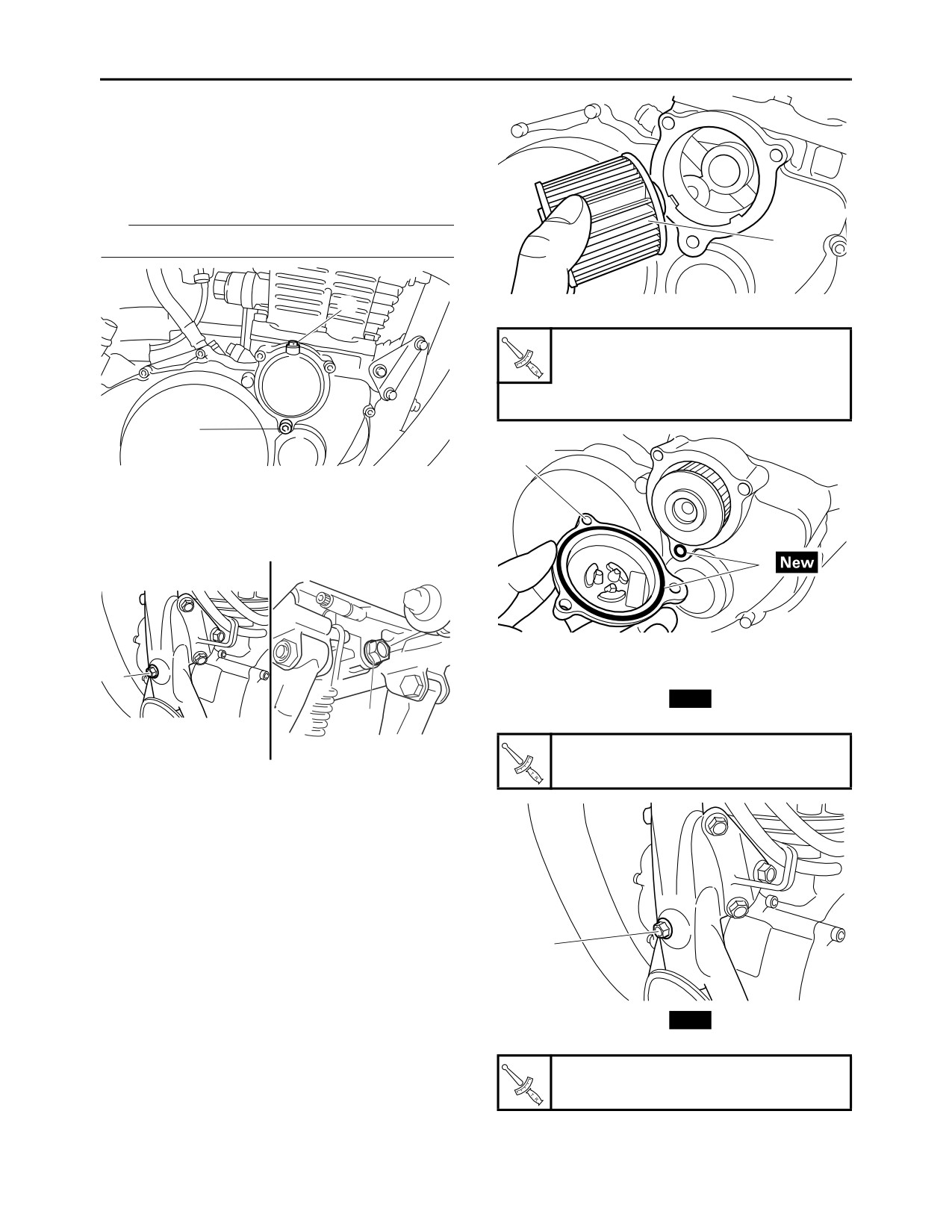
c. Install a new O-ring “2” and oil filter cover “3”.
Oil filter cover bolt
10 Nm (1.0 m·kgf, 7.2 ft·lbf)
Bleeder bolt
5 Nm (0.5 m·kgf, 3.6 ft·lbf)
2
3
4. Remove:
• Engine oil level gauge
• Oil drain bolt (oil tank side) “1”
• Oil drain bolt (crankcase side) “2”
2
▲▲▲▲▲▲▲▲▲▲▲▲▲▲▲▲▲▲▲▲▲▲▲▲▲▲▲▲▲▲▲▲
1
7. Install:
• Oil drain bolt gasket
New
2
• Oil drain bolt (oil tank side) “1”
Oil drain bolt
16 Nm (1.6 m·kgf, 12 ft·lbf)
5. Drain:
• Engine oil
(completely from the oil tank and the crank-
case)
6. If the oil filter element is also to be replaced,
perform the following procedure.
▼▼▼▼▼▼▼▼▼▼▼▼▼▼▼▼▼▼▼▼▼▼▼▼▼▼▼▼▼▼▼▼
a. Remove the oil filter cover and oil filter ele-
ment.
1
b. Install a new oil filter element “1”.
• Oil drain bolt gasket
New
• Oil drain bolt (crankcase side) “2”
Oil drain bolt
30 Nm (3.0 m·kgf, 22 ft·lbf)
3-22
PERIODIC MAINTENANCE
1
2
8. Fill:
b. Start the engine and check to see if oil seeps
• Oil tank
out while idling the engine for about one min-
(with the specified amount of the recom-
ute.
ECA2RD1003
mended engine oil)
NOTICE
Engine oil quantity
Any inspection must be conducted at engine
Quantity (disassembled)
idling speed. Do not rev up the engine.
2.40 L (2.54 US qt, 2.11 Imp.qt)
Without oil filter element replace-
c. If no oil seeps out, check the engine oil pas-
ment
sages, the oil filter element and the oil pump
2.00 L (2.11 US qt, 1.76 Imp.qt)
for damage or leakage.
With oil filter element replace-
d. Start the engine after solving the problem(s)
ment
and make sure that oil seeps out.
2.10 L (2.22 US qt, 1.85 Imp.qt)
e. Tighten the oil check bolt to specification.
9. Install:
Oil check bolt
• Engine oil level gauge
18 Nm (1.8 m·kgf, 13 ft·lbf)
10.Start the engine, warm it up for several min-
utes, and then turn it off. Before checking the
▲▲▲▲▲▲▲▲▲▲▲▲▲▲▲▲▲▲▲▲▲▲▲▲▲▲▲▲▲▲▲▲
engine oil level, wait a few minutes until the oil
EAS2RD1037
has settled.
CHECKING THE FRONT BRAKE LIGHT
11.Check:
SWITCH
• Engine
Refer to “ELECTRICAL COMPONENTS” on
(for engine oil leaks)
page 7-49.
12.Check:
• Engine oil level
EAS21330
ADJUSTING THE REAR BRAKE LIGHT
Refer to “CHECKING THE ENGINE OIL
SWITCH
LEVEL” on page 3-21.
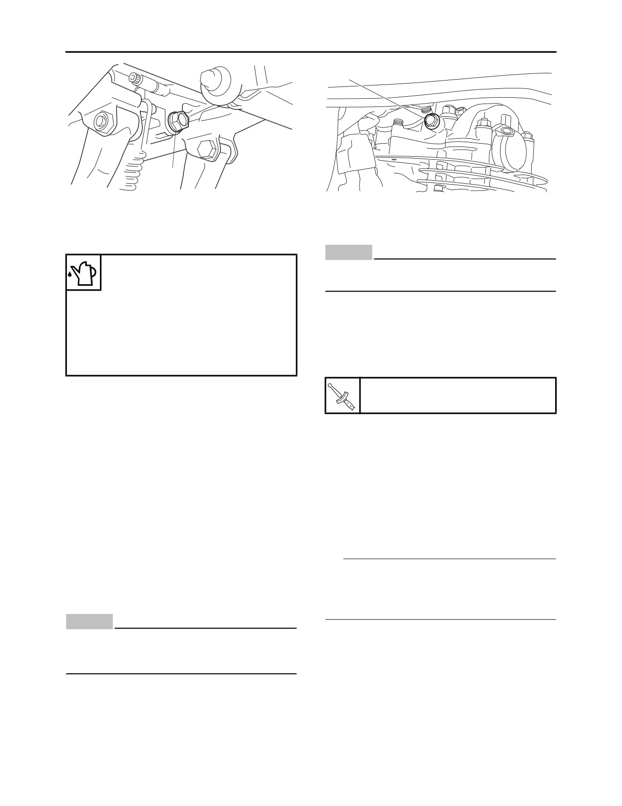
13.Check:
TIP
The rear brake light switch is operated by move-
• Engine oil pressure
ment of the brake pedal. The rear brake light
▼▼▼▼▼▼▼▼▼▼▼▼▼▼▼▼▼▼▼▼▼▼▼▼▼▼▼▼▼▼▼▼
switch is properly adjusted when the brake light
a. Slightly loosen the oil check bolt “1”.
ECA2RD1002
comes on just before the braking effect starts.
NOTICE
1. Check:
Engine start-up with the oil check bolt re-
• Rear brake light operation timing
moved will cause an oil spout. Check with
Incorrect Adjust.
the oil check bolt loosened without fail.
2. Adjust:
• Rear brake light operation timing
▼▼▼▼▼▼▼▼▼▼▼▼▼▼▼▼▼▼▼▼▼▼▼▼▼▼▼▼▼▼▼▼
a. Hold the main body “1” of the rear brake light
switch so that it does not rotate and turn the
adjusting nut “2” in direction “a” or “b” until the
rear brake light comes on at proper timing.
3-23
PERIODIC MAINTENANCE
Rough movement Lubricate or replace the
Direction “a”
defective part(s).
Brake light comes on sooner.
Direction “b”
Recommended lubricant
Brake light comes on later.
Suitable cable lubricant
TIP
With the engine stopped, turn the throttle grip
a
1
slowly and release it. Make sure that the throttle
grip turns smoothly and returns properly when
b
released.
2
Repeat this check with the handlebar turned all
the way to the left and right.
3. Check:
• Throttle grip free play “a”
Out of specification Adjust.
▲▲▲▲▲▲▲▲▲▲▲▲▲▲▲▲▲▲▲▲▲▲▲▲▲▲▲▲▲▲▲▲
Throttle grip free play
EAS21690
3.0-5.0 mm (0.12-0.20 in)
CHECKING AND LUBRICATING THE
CABLES
The following procedure applies to all of the in-
ner and outer cables.
EWA13270
a
WARNING
Damaged outer cable may cause the cable to
corrode and interfere with its movement. Re-
place damaged outer cable and inner cables
as soon as possible.
1. Check:
• Outer cable
4. Adjust:
Damage Replace.
• Throttle grip free play
2. Check:
▼▼▼▼▼▼▼▼▼▼▼▼▼▼▼▼▼▼▼▼▼▼▼▼▼▼▼▼▼▼▼▼
• Cable operation
Throttle body side
Rough movement Lubricate.
a. Loosen the locknut “1” on the decelerator ca-
Recommended lubricant
ble.
Suitable cable lubricant
b. Turn the adjusting nut “2” in direction “a” or “b”
to take up any slack on the decelerator cable.
TIP
c. Loosen the locknut “3” on the accelerator ca-
Hold the cable end upright and pour a few drops
ble.
of lubricant into the cable sheath or use a suit-
d. Turn the adjusting nut “4” in direction “a” or “b”
able lubricating device.
until the specified throttle grip free play is ob-
tained.
EAS30890
CHECKING THE THROTTLE GRIP
Direction “a”
1. Check:
Throttle grip free play is increased.
• Throttle cable
Direction “b”
Throttle grip free play is decreased.
Damage/deterioration Replace.
• Throttle cable installation
e. Tighten the locknuts “1” and “3”.
Incorrect Reinstall the throttle cables.
Refer to “HANDLEBAR” on page 4-33.
2. Check:
• Throttle grip movement
3-24
PERIODIC MAINTENANCE
EAS21770
b
CHECKING THE FUSES
a
a
4
Refer to “CHECKING THE FUSES” on page
b
7-57.
2
3
EAS21790
1
REPLACING THE HEADLIGHT BULB
1. Remove:
•S
crew “1”
•H
eadlight
unit a
ssembly “2”
TIP
If the specified throttle grip free play cannot be
obtained on the throttle body side of the cable,
use the adjusting nut on the handlebar side.
2
▲▲▲▲▲▲▲▲▲▲▲▲▲▲▲▲▲▲▲▲▲▲▲▲▲▲▲▲▲▲▲▲
▼▼▼▼▼▼▼▼▼▼▼▼▼▼▼▼▼▼▼▼▼▼▼▼▼▼▼▼▼▼▼▼
1
Handlebar side
a. Loosen the locknut “1”.
b. Turn the adjusting nut “2” in direction “a” or “b”
until the specified throttle grip free play is ob-
tained.
Direction “a”
Throttle grip free play is increased.
2
Direction “b”
Throttle grip free play is decreased.
1
c. Tighten the locknut.
2. Disconnect:
1
• Headlight coupler “1”
3. Remove:
• Headlight bulb cover “2”
2
1
2
a
b
EWA2RD1001
WARNING
After adjusting the throttle grip free play,
start the engine and turn the handlebars to
the right and to the left to ensure that this
4. Remove:
does not cause the engine idling speed to
• Headlight bulb holder “1”
change.
• Headlight bulb “2”
▲▲▲▲▲▲▲▲▲▲▲▲▲▲▲▲▲▲▲▲▲▲▲▲▲▲▲▲▲▲▲▲
EAS21760
CHECKING AND CHARGING THE BATTERY
Refer to “CHECKING AND CHARGING THE
BATTERY” on page 7-58.
3-25
PERIODIC MAINTENANCE
9. Install:
• Headlight unit assembly
• Screw
EAS21800
ADJUSTING THE HEADLIGHT BEAM
2
1. Adjust:
1
• Headlight beam (vertically)
▼▼▼▼▼▼▼▼▼▼▼▼▼▼▼▼▼▼▼▼▼▼▼▼▼▼▼▼▼▼▼▼
a. Loosen the adjusting screw “1” and move the
headlight unit in direction “a” or “b” for adjust-
EWA13320
ment.
WARNING
Since the headlight bulb gets extremely hot,
Direction “a”
keep flammable products and your hands
Headlight beam is raised.
away from the bulb until it has cooled down.
Direction “b”
Headlight beam is lowered.
TIP
Remove the headlight bulb holder by turning it
counterclockwise.
b
5. Install:
• Headlight bulb
New
Secure the new headlight bulb with the head-
light bulb holder.
a
ECA13690
1
NOTICE
Avoid touching the glass part of the head-
light bulb to keep it free from oil, otherwise
the transparency of the glass, the life of the
▲▲▲▲▲▲▲▲▲▲▲▲▲▲▲▲▲▲▲▲▲▲▲▲▲▲▲▲▲▲▲▲
bulb and the luminous flux will be adversely
affected. If the headlight bulb gets soiled,
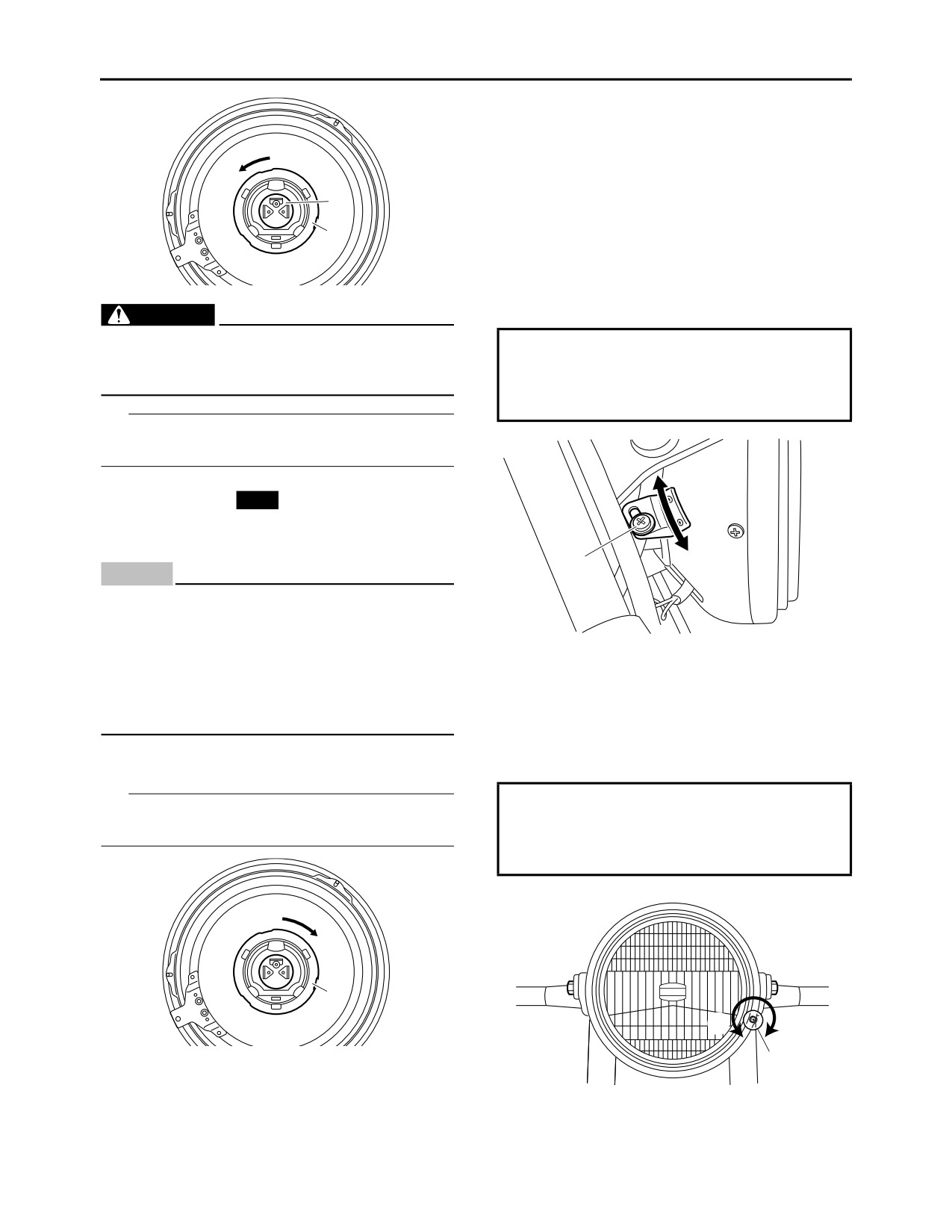
2. Adjust:
thoroughly clean it with a cloth moistened
• Headlight beam (horizontally)
with alcohol or lacquer thinner.
▼▼▼▼▼▼▼▼▼▼▼▼▼▼▼▼▼▼▼▼▼▼▼▼▼▼▼▼▼▼▼▼
a. Turn the adjusting screw “1” in direction “a” or
6. Install:
“b” for adjustment.
• Headlight bulb holder “1”
TIP
Direction “a”
Install the headlight bulb holder by turning it
Headlight beam moves to the right.
clockwise.
Direction “b”
Headlight beam moves to the left.
1
b
a
7. Install:
1
• Headlight bulb cover
8. Connect:
▲▲▲▲▲▲▲▲▲▲▲▲▲▲▲▲▲▲▲▲▲▲▲▲▲▲▲▲▲▲▲▲
• Headlight coupler
3-26